#include <stdlib.h>#include <stdbool.h>#include "freertos/FreeRTOS.h"#include "driver/gpio.h"#include "esp_log.h"#include "esp_err.h"#include "pin_defs.h"#include "motor_driver.h"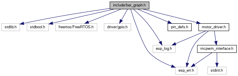
Go to the source code of this file.
Functions | |
| esp_err_t | enable_bar_graph () |
| enables the bar graph led's gpio pins More... | |
| esp_err_t | set_bar_graph (uint8_t data) |
| Set the value of bar graph LED. More... | |
| uint8_t | bool_to_uint8 (bool *input_array) |
| converts a boolean array of size 8 into 8-bit unsigned integer More... | |
Function Documentation
◆ bool_to_uint8()
| uint8_t bool_to_uint8 | ( | bool * | input_array | ) |
converts a boolean array of size 8 into 8-bit unsigned integer
- Parameters
-
input_array boolean input array of size 8
- Returns
- uint8_t returns a 8 bit number formed after combining the boolean array
◆ enable_bar_graph()
| esp_err_t enable_bar_graph | ( | ) |
enables the bar graph led's gpio pins
It will check for state of motor driver A, and accordingly init the free gpios.
| Motor Driver A | Mode |
|---|---|
| off | 0 |
| parallel | 1 |
| normal | 2 |
enabled_bar_graph_flag is set to the value of Mode accordingly.
- Returns
- esp_err_t returns ESP_OK if enabled correctly, and ESP_FAIL if it failed to initialise
◆ set_bar_graph()
| esp_err_t set_bar_graph | ( | uint8_t | data | ) |
Set the value of bar graph LED.
The exact working of this is a bit hard to understand, so this is example. Below are the given states of motor drivers
Motor Driver A: Normal Mode = 2, so for mode = 2, mask = bitmask[2] = 0x0F = 00001111 data = 0xAA = 10101010
Since, motor driver A is in normal mode, we can only use IN5, IN6, IN7, IN8 pins of the bar graph LED
Mask ==> 00001111 => 0x0F
Now, if data is 10101010, then even though pins IN1-IN4 are being used by motor driver, it will be set by gpio_set_level, which will crash the esp32 device. So, we check in the bitmask if the following pin is free or not, if bit is 1, it can be used, if it is 0, then it can't be used.
So, to achieve this we bitwise-and the mask with 0x80(10000000), if result is 0x80, then leftmost bit is 1, else it is 0. If leftmost bit is 1, means we can use this pin of bar graph, then we do the same thing with data, bitwise-and it with 0x80, to find the leftmost bit, if it is 1, the pin is set to 1, else 0. Now we left shift the data and mask variable.
- Parameters
-
data 8bit binary in hexadecimal form, i.e, the pattern that is needed to be shown on the bar graph LED
- Returns
- esp_err_t returns ESP_OK